The basics of TIG welding
- Useful information on TIG welding
- Selection of welding consumable
- Setting the shielding gas quantity
- Cleaning workpiece surfaces
- Ignition of the arc
- Guiding the TIG welding torch
- Welding position
- Welding parameters
- Welding with electrical impulses
- Necessary equipment
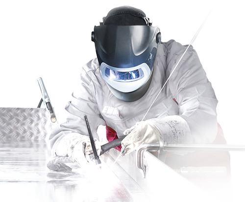
Useful information on TIG welding
TIG welding is an all-purpose welding procedure with regard to materials used, wall thickness and welding positions. It allows top-quality welded joints to be produced. Identified as tungsten inert gas welding in DIN 1910 – Part 4, the TIG welding procedure has its origins in the US, where it first went by the name of argon arc welding in 1936. It was not introduced in Germany until after the 2nd World War. In English-speaking countries, the T in TIG welding refers to tungsten. The process outperforms other fusion welding procedures thanks to a series of interesting advantages. Its suitability for a wide range of tasks is one such advantage.
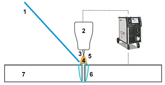
- Welding rod
- Welding torches
- Tungsten electrode
- Arc
- Shielding gas
- Weld pool
- Parent metal
If a metallic material is at all suited to fusion welding, then you can use this process to join the material. It is also a very 'clean' process, which produces hardly any spatter and few pollutants while also guaranteeing a high-grade welded joint if used properly. Another special advantage of TIG welding is that the feeding of welding consumable and the current are not interlinked, unlike in other processes which work with consumable electrodes. The welder is thus able to optimally adjust the current to the welding task concerned and only add as much welding consumable as needed at any given time. This makes the process particularly suitable for welding root passes and positional welding. These advantages mean that the TIG process is successfully used in many sectors of trade and industry today. However, a welder's skilled hand and excellent training are still required for manual welding. This guide seeks to explain the special features of the process and possibly arouse interest in companies which do not yet use it for suited welding tasks despite its ready availability.
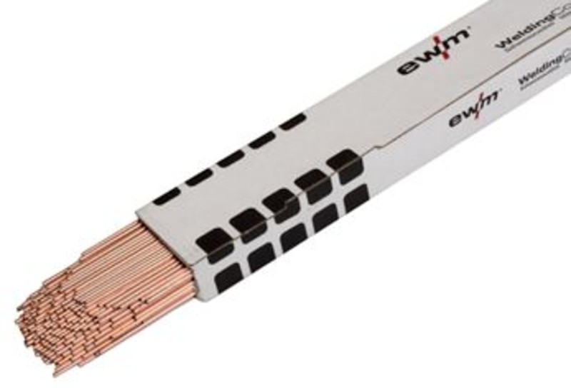
Selection of welding consumable
The welding consumable used during TIG welding is usually rod-shaped. In the fully mechanical method, it is fed in wire form through a separate feed mechanism. Welding consumables are usually selected in the same way as the parent metal. However, for metallurgical reasons, it is necessary for the welding consumable to deviate from the parent metal when certain alloying elements are used. For crack resistance purposes, this must be kept at a very low level, e.g. In the case of carbon content. In such cases, similar types of welding consumables are used. However, there are cases in which dissimilar types of welding consumables are needed. For example, when joining C-steels which are difficult to weld, austenitic welding consumables or even nickel-based alloys are used. The diameter of the welding consumable must be adjusted to the welding task. This depends on the material thickness, and therefore also on the diameter of the tungsten electrode. Welding rods are usually 1000 mm in length. They are delivered in bundles, and should be labelled individually with the DIN or trade name, to avoid confusion.
Setting the shielding gas quantity
The shielding gas quantity is set as a flow rate in l/min. This depends on the size of the weld pool and therefore on the electrode diameter, the gas nozzle diameter, the nozzle distance to the base material surface, the surrounding air flow and the type of shielding gas – see the Shielding Gas section. A rule of thumb states that 5 to 10 litres of shielding gas should be added to argon as the shielding gas, and to the most widely used tungsten electrode diameters, at a rate of 1 to 4 mm per minute. The flow rate can be measured indirectly using manometers in front of a built-in nozzle, which measure the pressure in proportion to the flow rate. The scale of the manometer is directly calibrated in l/min. More specifically, measuring instruments that measure directly using glass tubes and float type meters measure the protective gas flowing to the welding torch.
Cleaning workpiece surfaces
 For good welding results, it is important to thoroughly clean the fusion faces and the surfaces of the workpiece in the welding area, before starting the welding process. The surfaces should be metallically bright and free from grease, rust, dirt and paint. Scale layers should also be removed where possible. In many cases, brushing will suffice. Where this is not sufficient, the surface must be treated by grinding or by means of a mechanical processing method. Only brushes made of stainless steel may be used for corrosion-resistant materials, or else rust may be caused by iron particles on the surface. In the case of aluminium, it is important that there is not a thick oxide skin on the surface, so that pores can form. Suitable solvents must be used for cleaning and lubricating. Please note: Toxic vapours may be emitted by solvents containing chlorine.
Ignition of the arc
The arc should never be ignited outside the joint on the parent metal, but always so that the ignition point can be melted again immediately after welding. At the beginning of the welding process, the high-temperature parent metal at the ignition point cools down very quickly due to the extraction of heat by the cold masses at the end. The result of this rapid cooling can be hardening, and may cause cracks and pores. This rapid cooling can be avoided if the ignition takes place directly at the weld start, and any flaws which may arise are re-melted immediately. Contact ignition should be the absolute exception if an older welding device which does not have an ignition aid (high-voltage pulse ignition) is used. In this case, copper plates are inserted into the joint in the vicinity of the weld start. From here, the arc is guided to the intended start of seam and the welding process begins. In the case of contact ignition directly on the parent metal, tungsten can enter the weld metal which is not fused due to the high melting point, and can later be detected as a bright spot in the radiographic film because of the greater absorption of x-rays by tungsten.
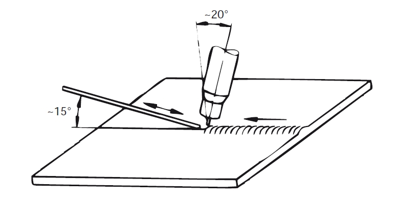
Guiding the TIG welding torch
(see illustration on the right)
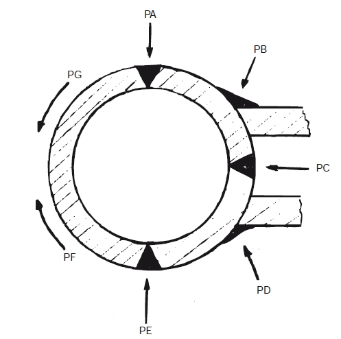
Welding position
The welding positions are labelled PA - PG, in accordance with ISO 6947. When viewed from the top of the pipe (PA), these are arranged clockwise in alphabetical order. The PA position was previously known as a horizontal or flat position in Germany. This is followed by the butt weld positions PC (horizontal on the vertical wall) and PE (above), as well as the filler positions PB (horizontal) and PD (horizontal/above). When welding sheet metal, PF is welded vertically, and PG is the vertical-down weld. However, several positions are combined on the pipe. The position PF applies when the pipe is welded from above without turning to either side. The position PG applies to the welding from top to bottom (vertical-down weld). TIG welding is possible in all positions. The welding data must match the position, as in other welding procedures.
Welding parameters
The lower limit of the application of the TIG process is about 0.3 mm for steel and 0.5 mm for aluminium and copper. Towards the top, economic limits are set for the application. The deposition rate rate is not very high in this process. For this reason, only the root passes are TIG welded, and the remaining layers are welded using other processes (E, MAG), which have a higher power. When selecting the welding parameters, it must be noted that only the current is set on the welding device. The arc voltage is determined by the arc length, which is maintained by the welder. Therefore, the greater the arc length, the higher the arc voltage. A welding current of 45 amps per mm of wall thickness is used as the reference value for a current sufficient for welding steel with a direct current to full penetration. For AC welding aluminium, a current of 40 amps/mm is required.
Welding with electrical impulses
When welding with a pulse current, the current intensity and the voltage constantly change between a low basic value and a higher pulse value, according to the pulse frequency. Under the influence of the high pulse current, the penetration is takes place in the parent metal and a point-shaped weld pool is formed. This begins to solidify from the edge under the impact of the lower basic current, until the next current pulse melts it again and increases it. In the meantime the arc has already spread at the welding speed so that the weld seam is formed from many overlapping spots during TIP pulsed welding. The size of the weld pool is, on average, smaller than if welding with a uniform current, so that it can be better contained during positional welding. However, adequate penetration is still ensured. The aforementioned effect only occurs if there is a sufficient temperature difference in the weld pool between the basic and impulse phases. This only occurs if the pulse frequency is below approximately 5 Hz. A disadvantage is that the welding speed must be reduced frequently during pulsed welding. The welder is also alerted of pulsing in the low frequency range if the arc flickers in a disruptive manner. This variant of TIG welding is therefore less frequently used in manual welding, whereby the welder has other possibilities for controlling the weld pool. However, it is more common in mechanised TIG welding.
The following equipment is required for successful TIG welding:
- Power source
- Welding torches
- Work clamp / grounding tongs
- Stick electrode
- Welding tools
- Work clothing
More information on TIG welding can be found in our Welding dictionary.