Materials for TIG welding
- Characteristics of various materials
- Unalloyed and low-alloy steels
- Austenite CrNi steels
- Aluminium and aluminium alloys
- Copper and copper alloys
- Other materials
Characteristics of various materials
As previously mentioned, the TIG process is suitable for welding a wide range of materials. Some materials are welded with direct current, others with alternating current. The following is a list of some of the special characteristics of the different materials.
Unalloyed and low-alloy steels
 These steels can be joined with all fusion welding procedures. However, a welding procedure is usually selected on the basis of economic considerations, rather than quality aspects. The TIG process is therefore under-represented due to its low performance with these steels. An exception is the welding of root passes. For wall thicknesses greater than 6 mm, only the root is TIG welded and the other layers are added using a more powerful process. Another exception is the welding of pipes with smaller diameters. The TIG method is best suited to this. A particular feature is that pores may form, e.g. in the case of unalloyed tube steels (e.g. P235) which contain little silicon, or when welding in such pipes in boiler floors. In addition, pores may form in deep-drawing steels which can only be softened with aluminium, when they are welded with a small amount of welding consumable. Due to the absorption of oxygen from the atmosphere, which cannot be completely prevented during gas shielded arc welding, the weld metal is non-effervescent, and pores can be formed through the build-up of carbon monoxide in the weld metal. The remedy must contain as much Si/Mn-alloyed welding consumable as possible, so that the oxygen harmlessly cures the material.
Austenite CrNi steels
These materials are particularly suitable for TIG welding, because of the favourable viscosity of the weld metal. Smooth surfaces and flat root surfaces are formed. However, due to the relatively low welding speed of the TIG process, and the low thermal conductivity of CrNi steels, small wall thicknesses can easily lead to overheating. This may result in hot cracking, and the corrosion resistance can be reduced. Where necessary, overheating can be avoided with cooling periods or by cooling the workpieces. This also reduces the distortion, which is greater for CrNi steels because the expansion coefficient is greater than that of unalloyed steel. In the case of components which are subsequently exposed to a corrosive attack, the oxide skins and discolouration of the seam surface and at the edges on both sides in the parent metal which are caused by welding must be removed by brushing, blasting, grinding or pickling before the component is put into operating mode. There is an increased risk of corrosion under these skins. This also applies to the root side when welding pipes. Because mechanical processing is rarely possible here, forming is recommended in order to avoid oxidation.
Aluminium and aluminium alloys
 When welding aluminium materials, alternating current is used, except for in certain cases which will be described later. This is necessary to avoid the refractory oxide layer on the component. Aluminium oxide (Al203) has a melting point of around 2050°C. The parent metal, e.g. pure aluminium, however, melts at 650°C. Aluminium has such a great chemical similarity to oxygen that even if the surface of the parent metal has been made oxide-free by brushing or scraping, such skins will quickly reappear on the surface. Due to their high melting point, these will melt only partially under the arc. Most of the weld surface would be covered with a solid layer of aluminium oxide when welding with direct current (pol). This makes the monitoring of the pool impossible, and the addition of welding consumable very difficult. Although this oxide layer can be removed by using fluxes, as in brazing, this would mean an additional outlay.
When welding with alternating current, it is possible to tear and remove this oxide layer, by means of charge carriers in the arc. Only ions are suitable for this, since electrons have insufficient kinetic energy due to their low mass. If the negative pole is at the electrode, the electrons will move from the electrode to the workpiece, and the remaining ions from the workpiece to the electrode. With this polarity, a cleaning effect is not possible. Conversely, when the polarity is reversed, heavier ions move towards the surface of the workpiece. Due to their kinetic energy, they can tear and remove the oxide layer. However, welding on the hotter positive pole would result in a very low current-carrying capacity for the electrode. This variant of TIG welding is therefore only suitable for welding very thin aluminium structures (with a wall thickness of up to about 2.5 mm). The alternating current offers a compromise. The cleaning effect occurs when the positive half-wave is on the electrode. The electrode can then cool down again in the subsequent negative half-wave. These are therefore known as the cleaning and cooling half-waves. When welding with alternating current, the current-carrying capacity is lower than when welding with direct current and a negative pole. However, it is significantly higher than when welding with a positive pole. It is evident that for a sufficient cleaning effect, 20 or 30% of the positive half-wave (as opposed to the entire half-wave) is adequate.
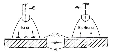
| Cleaning using kinetic energy | Electrodes on the positive pole |
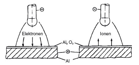
| No cleaning | Electrodes on the negative pole |
This is used for modern TIG power sources. An artificial rectangular alternating current is generated, whereby the positive and negative poles of a direct current source are switched to the electrode by quickly reacting switches (transistors). The balance of the two half-waves can be adjusted relative to one another, e.g. from 20 % plus / 80 % minus to 80 % plus / 20 % minus. The lower proportion of the positive pole results in a higher current-carrying capacity for the electrode, or in the case of equal current settings, to a longer service life.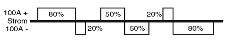 In these so-called “square-wave sources”, the frequency of the artificial alternating current can usually be altered, e.g. between 50 and 300 Hz. Increasing the frequency also protects the electrode.
The square-shaped artificial alternating current has yet another advantage. Because the current course is very high when the polarity is changed, the delay times of the arc during the zero crossing are substantially shorter than in the case of a sinusoidal progression. Re-ignition is therefore more secure, even without an ignition aid, and the arc is generally more stable. However, a louder buzzing sound is noticeable in the re-ignition process. Modern TIG power sources allow welding with direct current, as well as with sinusoidal and rectangular alternating current. Recently, a variant of TIG negative pole welding has come into use, in which shielding gas containing a large amount of helium (e.g. 90 % He / 10 % Ar) is used. As previously explained, the oxide skin cannot be broken when welding to the negative pole. However, due to the high temperature of the heat-resistant helium arc, it can be liquefied. It is therefore only a little bit disruptive. TIG direct current negative pole welding under helium is used for castings made of aluminium-silicon alloys, due to the better penetration characteristics, especially when repair welding.
An additional special characteristic of welding the material aluminium is its pore sensitivity when hydrogen is absorbed. The conditions are much more critical than those of steel welding. Whereas iron has a hydrogen solubility of 8 cm3 / 100 g of weld metal during the transition from a liquid to a solid state, aluminium has practically no hydrogen solubility in its solid state. This means that all hydrogen absorbed during welding must leave the weld metal before it solidifies. Otherwise, pores will form in the weld metal.
 The primary sources of hydrogen in the TIG welding of aluminium are the oxide skins on the parent metal. These trap moisture, and must therefore be removed by brushing or scraping before welding. On the other hand, the arc is quieter when there is a thin oxide layer on the surface, as this emits more electrons than the pure metal. A compromise must therefore be found between a stable arc and adequate porosity. It has proven to be advantageous to thoroughly remove oxides from the surfaces of the workpieces prior to welding, and then to delay the welding by another one or two hours, so that a thin oxide layer can form. The oxide skins on the surface of the welding rods also contribute to pore formation. Aluminium welding consumable should therefore be stored carefully, and not for too long.
Copper and copper alloys
 The welding of copper is particularly difficult due to its high thermal conductivity. Therefore, in the case of greater material thicknesses, at least the start of the weld seam must be preheated. Subsequently, a preheating effect is produced by the advance welding heat, so that large-scale preheating is only required for wall thicknesses > 5 mm. With the TIG method, it is possible to use the arc itself for preheating, whereby heat is fed through by using the extended arc to make circular movements on the start of the weld seam. Pure copper and many Cu alloys are welded using direct current and a negative electrode. Only some bronzes, such as brass and aluminium bronze, are better welded with alternating current.
Other materials
Out of the materials already mentioned, nickel and nickel alloys are still TIG-welded to a significant extent. The main ones are nickel/chromium alloys (e.g. inconel) and nickel/copper alloys (e.g. monel). Titanium and titanium alloys are also TIG welded. A direct current with a negative electrode is best suited to these materials. However, when welding titanium, the area around the weld seam has to be protected by shielding gas, and shielding gas must also be provided at a further distance from the welding point, as well as on the back, by quenches to avoid discolouration. Otherwise, the material will absorb atmospheric gases and become brittle.