Basic concepts of MIG/MAG welding
- General information on MIG/MAG welding
- Current type
- Tips for correct MIG/MAG welding
- Igniting the arc
- Moving the torch
- Ending the welding process
- Welding parameters
- What you need
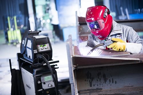
General information
As defined in ISO 857-1, the new generic term for all arc welding processes in Germany, where a wire electrode is melted using shielding gas, is gas-shielded metal arc welding (process no. 13). The generic term formerly used in Germany was metal shielding gas welding. The ISO standard defines the process as follows: Metal arc welding using a wire electrode whereby gas from an external source surrounds the arc and the weld pool to protect them from the atmosphere. Depending on the type of shielding gas being used, there are further sub-classifications into metal inert gas welding (MIG), process no. 131, when an inert gas is used and metal active gas welding (MAG), process no. 135, when an active gas is used.
Other variants also listed in ISO 857-1 are: Flux cored wire welding with active gas (process no. 136), flux cored wire welding with inert gas (process no. 137), plasma MIG welding (process no. 151) and electrogas welding (process no. 73). MIG/MAG welding is characterised in that a wire electrode supplied from the spool by a wire feed motor is powered by the contact tip shortly before leaving the welding torch so that the arc can burn between the end of the wire electrode and the workpiece. The shielding gas flows out of the shielding gas nozzle, which surrounds the wire electrode concentrically.
The weld metal is therefore protected from being penetrated by the atmospheric gases oxygen, hydrogen and nitrogen. In addition to its protective function, the shielding gas has other purposes. As it determines the composition of the arc atmosphere, it also affects its electrical conductance and thus the welding characteristics. Furthermore, it also affects the chemical analysis of the resulting weld metal through the pick-up and burn-off processes, it also has a metallurgic effect.
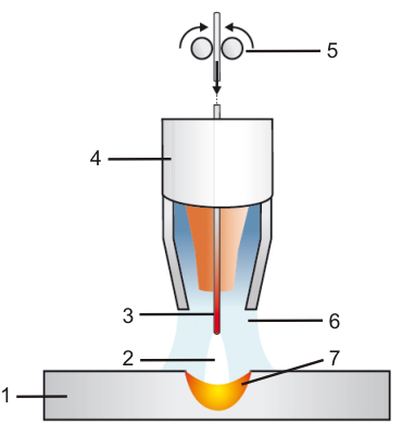
- Workpiece
- Arc
- Wire electrode
- Gas nozzle
- Wire feeder
- Shielding gas
- Weld pool
Current type
Apart from a few recent exceptions, MIG/MAG welding is performed using direct current, with the plus pole of the power source on the electrode and the minus pole on the workpiece. With some flux cored wires, the reverse polarity is also occasionally used. In more recent times, alternating current is also used for very special applications, e.g. for MIG welding on very thin aluminium sheets.
Tips for correct MIG/MAG welding
The MIG or MAG welder requires good training, not only in practical welding but also in terms of the theoretical features of the procedure. This helps him to avoid mistakes.
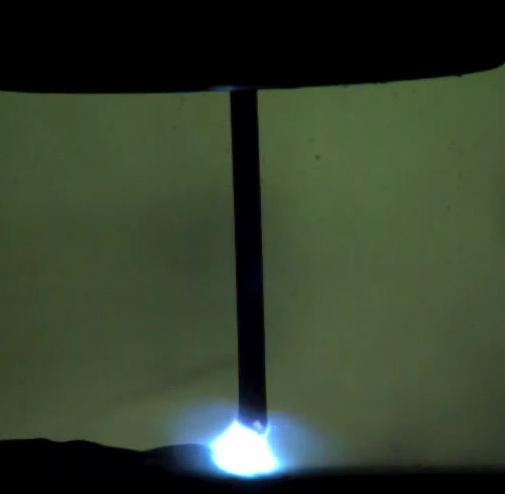
Igniting the arc
After the torch switch is pressed, the wire electrode starts moving at the previously set speed.
At the same time, it is made live via the power relay and the shielding gas begins to flow. When touching the surface of the workpiece, a short circuit occurs. Owing to the high current density at the tip of the electrode, material starts vaporising at the point of contact and the arc ignites.
At high wire feed rates, the still very weak arc may be stifled by wire material pressing onto it, as a result, the ignition process may only succeed after the second or third attempt.
It is therefore more practical to ignite at a reduced feed speed and only once the arc is burning steadily switch to the actual wire feed speed. Newer types of MIG/MAG systems offer the option of setting what is known as a “wire creep speed”.
Ignition should never be performed outside the gouge and only in such places, which are melted down immediately afterwards. Owing to the high cooling rate of such locally heated spots, crack formation may occur in ignition points that have not been overlapped.
Moving the torch
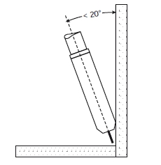
The welding torch is tilted in the direction of welding by around 10 ° to 20 ° and can be dragged or pushed. Its distance to the workpiece should be such that the free wire end, i.e. the distance between the lower edge of the contact tip and the start point of the arc, is about 10 - 12 times the wire diameter [mm]. If the welding torch is tilted too much, there is a risk that air is sucked into the shielding gas.
When welding solid wires, forehand torch movements are generally used. Backhand welding is used with slag-forming flux-cored wires. The welding torch is normally moved using a slightly backhand motion in the PG position. Vertical down welding (PG pos.) is mainly used with thinner sheets.
In thicker sheets, there is a risk of lack of fusion owing to weld metal running ahead. Lack of fusion caused by weld metal running ahead may also occur in other positions if welding is performed at too low a welding speed. Wide weaving movements should therefore be avoided wherever possible, except in the PF position. The open triangle is the usual form of weaving movement.
Ending the welding process
At the end of the seam, the arc must not be suddenly shut down or the welding torch removed from the end-crater. Particularly with thicker sheets where deep end-craters may occur in large-volume runs, removing the arc slowly from the bath is more advisable, or setting an end crater program, if the system being used permits this. With most systems, a specific post-flow time can also be set for the shielding gas, this means that the last molten weld metal remaining can embrittle under the shielding gas coverage. This is only effective, however, if the welding torch is held for a time at the end of the seam.
Welding parameters
The lower limit for the possible use of the process for butt welds with unalloyed steel is around 0.7 mm, with stainless steel 1 mm and with aluminium materials around 2 mm. Root passes and thin sheets are normally welded using a short arc or using a lower power range pulsed arc. With filler, final and backing runs on thicker panels, spray or long arcs are set with higher power range.
These welding tasks can also be performed with very low spatter using the pulsed arc. The current and voltage values used by the welder for information purposes can be read from the measuring instruments, which are usually installed in the machines. With pulsed welding, the display instruments show the arithmetic average value of the current and arc voltage produced in the pulse and base phase at the set pulse frequency.
The tables can therefore also be used as guideline values for pulsed MIG/MAG welding. External measuring devices can be used if no measuring devices are integrated into the machine, or the welder must refer to the wire feed speed also given in the tables. The welder must then set the correct arc length according to what can be seen and heard.
The following equipment is required for successful MIG/MAG welding:
For more information on the subject of MIG/MAG welding, see our welding dictionary.