MMA basics
- General information on MMA welding
- Current type
- Electrode type
- Characteristics of the coating types
- MMA welding done the right way
- Igniting the arc
- Guiding the electrode
- Magnetic arc blow
- Welding parameters
- Current based on electrode diameter
- Required equipment
General information
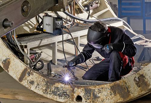
MMA welding (process number 111) is a fusion welding procedure. More precisely, it is a metal arc welding procedure. ISO 857-1 (1998 edition) explains the welding processes in this group.
Metal arc welding: Arc welding process that uses a consumable electrode. Metal arc welding without gas protection: Metal arc welding process without externally added shielding gas and manual metal arc welding: Manually performed metal arc welding that uses a coated electrode.
In Germany, the latter method is known as manual arc welding (Lichtbogenhandschweissen), MMA welding (E-Hand-Schweissen), or electrode welding (Elektrodeschweissen). In English-speaking countries, the abbreviations MMA or MMAW (Manual Metal Arc Welding) are widely used. It is characterised by the fact that the arc burns between a melting electrode and the weld pool. It does not involve external protection; all protective effects against the atmosphere come from the electrode itself. The electrode serves both as the arc conductor and the welding consumable. The coating forms slag and/or shielding gas, which (among other things) protects the transferring drops and the weld pool from the entry of atmospheric gases oxygen, nitrogen, and hydrogen.
Current type
Generally speaking, both direct current as well as alternating current can be used for arc welding (MMA welding), but not all of the stock electrode's coating types can be welded with sinus alternating current, e.g. purely basic electrodes cannot be used. With most electrode types, when welding with direct current, the negative pole is connected to the electrode and the positive pole is connected to the workpiece. Here as well, the basic electrodes are the exception. It is better to connect them to the positive pole. The same applies to the cellulose electrodes from some manufacturers. More information is available in the section “Electrode types”. The electrode is the welder's tool. The welder guides the arc that is burning on the electrode into the weld gouge, thereby melting the gouge edges; see Figure 2. Various currents are required depending on the type of gouge and the thickness of the parent metal. Since the current-carrying capacity of the electrodes is limited according to their diameter and length, the stick electrodes are available in a variety of diameters and lengths. Table 1 shows the dimensions that are standardized in DIN EN 759. Higher welding currents can be applied as the rod diameter increases.
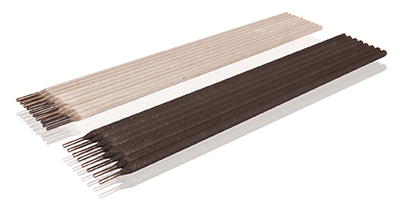
Electrode types
Stick electrodes are available with coatings comprised of varying components. The structure of the coating determines the electrode’s deposition characteristics, its welding properties, and the quality of the weld metal (see Section “Choosing the right electrode for your purposes”. According to DIN EN 499, stick electrodes for welding unalloyed steels can have various coating types. It is thereby important to distinguish between general types and mixed types. The letters used to designate the types are taken from the first letter of the electrode type. C=cellulose, A=acid, R=rutile, and B=basic. In Germany, the rutile type is the dominant type. Stick electrodes may have a thin, medium, or thick coating. For this reason, the thick-coated rutile electrodes, which are common in all three coating types, are designated as RR in order to avoid confusion. Alloyed and high-alloy stick electrodes do not have this variety of coating types. Stick electrodes for welding stainless steel (standardized in DIN EN 1600), are distinguished only as rutile electrodes and basic types, likewise for stick electrodes for welding creep-resistant steel (DIN EN 1599), although rutile electrodes are available as rutile-basic mixed types without special designation. This is true, for example, for electrodes that have better welding properties in positional welding. Stick electrodes for welding high tensile steel (DIN EN 757) are available only with a basic coating.
Characteristics of the coating types
The composition and thickness of the coating influences the welding characteristics to a particularly high degree. This is due both to the stability of the arc as well as to the material transfer during welding and the viscosity of the slag and weld pool. The size of the droplets transferring in the arc is of particular significance.
 The image schematically depicts the droplet transfer of the four general types of coatings. Cellulose (a), rutile (b), acid (c), and basic (d).
The coating consists primarily of organic components that burn in the arc and thereby form shielding gas that protects the welded point. Aside from cellulose and other organic substances, the coating contains only small amounts of arc-stabilizing substances, so hardly any slag forms. Cellulose types are particularly well suited for vertical down welding because slag inclusion is not a problem.
The acid type's (A) coating consists largely of iron ore and manganese ore and provides larger volumes of oxygen for the arc atmosphere. The oxygen is also absorbed by the weld metal, reducing its surface tension. This results in a very fine, spray-like material transfer and a low viscosity weld metal. Because of this, electrodes of this type are not suitable for positional welding. The arc also runs very “hot”, which permits high welding speeds but tends to form undercuts. Due to these disadvantages, stick electrodes of the pure acid type are rarely used in Germany.
Instead, the rutile-acid (RA) type, a mixture of acid and rutile electrodes, is used. The electrode also has corresponding welding properties. The coating of the rutile type (R/RR) consists largely of titanium dioxide in the form of the minerals rutile (TiO2) or ilmenite (TiO2. FeO) or synthetic titanium dioxide. The electrodes of this type are characterized by a material transfer with fine to medium droplets, a steady, low-spatter melt, very fine seam formation, good removability of slag, and good re-ignition properties. The latter is observed in this form only with rutile electrodes with a high proportion of TiO2 in the coating. As a result, electrodes that have already been melted once can be re-ignited without removing the coating crater. If the TiO2 content is high enough, the slag film that forms in the crater has a conductivity that is almost as high as a semiconductor so when the edge of the crater is set onto the workpiece, so much current flows that the arc may ignite without the core rod contacting the workpiece. Such spontaneous re-ignition is important when the welding process is frequently interrupted, e.g. when there are short seams.
In addition to the pure rutile type, there are a few mixed types in this group of electrodes. On the rutile-cellulose (RC) type, some of the rutile is replaced by cellulose. Since cellulose burns during welding, less slag forms. This type can therefore be welded in a vertical-down weld (Pos. PG) However it also has good welding properties in most other positions.
The rutile-basic (RB) type is another mixed type. It has a somewhat thinner coating than the RR type. This and the special slag characteristics make it particularly well suited to welding in the vertical up position (PF). This leaves the basic type (B). In this case, the coating consists largely of the basic oxides of calcium (CaO) and magnesium (MgO), which are added as the slag thinner calcium fluoride (CaF2). At higher levels, the calcium fluoride reduces the AC welding capability. Purely basic electrodes may therefore not be welded on sinus alternating current, although there are mixed types with less calcium fluoride in the coating, which may be used on this current type. Basic electrodes exhibit medium to coarse material transfer and the weld pool is viscous. The electrode welds well in all positions. However, the resulting runs are somewhat vaulted and coarsely ruffled due to the higher viscosity of the weld metal. The weld metal has very good toughness characteristics.
Basic coatings are hygroscopic. Therefore, it is important to carefully maintain dry storage conditions of the electrodes. If electrodes contact moisture, they must be dried out. But if the electrodes are welded dry, the weld metal possesses a very low hydrogen content. In addition to stick electrodes with normal metal recovery (<105 %) there are also those with higher metal recovery (usually >160 %) due to iron powder that is added through the coating. These electrodes are known as iron powder types or high performance electrodes. Due to their high deposition rate, they are more economical than normal electrodes in many applications, although they are usually limited to level (PA) and horizontal (PB) positions.
MMA welding done the right way
The welder must be properly trained, not just as a craftsman, but also in the relevant technical aspects, in order to avoid mistakes. The educational guidelines of the German Association for Welding and Related Methods (DVS) are recognised around the world and have been adopted by the International Institute of Welding (IIW). Before welding begins, the workpieces are usually tacked. The tack points must be long and thick enough so that the workpieces cannot contract too much during welding and break the tack points.

- Workpiece
- Weld seam
- Slag
- Arc
- Coated electrode
- Electrode holder
- Power source
Igniting the arc
During MMA welding, the welding process is initiated by way of touch starting. To establish the current circuit, the welder must first create a short circuit between the electrode and the workpiece and then immediately lift the electrode slightly, causing the arc to ignite. The ignition process must never occur outside of the gouge, but instead only at locations that will be melted again immediately after the arc burns. If ignition occurs anywhere else, the sudden warming may cause cracks, especially if working with sensitive materials. When using basic electrodes that tend towards initial porosity, ignition must occur significantly sooner than the actual start of welding. The welder then guides the arc back to the starting point of the seam and, as he continues welding, the initially deposited droplets (mostly porous) are re-melted.
Guiding the electrode
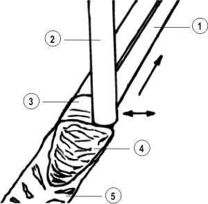
The electrode is positioned vertically or at a slight angle relative to the surface of the metal panel. It is inclined slightly in the direction of welding. The visible arc length, i.e. the distance between the edge of the crater and the surface of the workpiece, should thereby be about the same as the diameter of the core rod. Basic electrodes must be welded with a very short arc (distance = 0.5 x core rod diameter). To ensure this, they must be guided at a steeper angle than rutile electrodes. In most positions, the welder creates a stringer bead or weaves slightly with a gouge width that gets larger as it moves up. Weave beads are drawn across the entire width of the gouge only in position PF. Welding is usually a dragging motion; the electrode is pushed in position PF only.
- Welding bevel
- Stick electrode
- Liquid weld metal
- Liquid slag
- Cooled slag
Magnetic arc blow
Arc blow refers to a phenomenon whereby the arc is deflected from its centre axis and extended, emitting a hissing noise. This deflection may result in discontinuities. Penetration may become inadequate and - in the case of slag-forming welding processes - slag running may cause slag inclusions in the seam. The deflection is caused by forces that originate from the surrounding magnetic field. Like all current-carrying conductors, electrodes and arcs are surrounded by a ring-shaped magnetic field. This field is deflected in the area of the arc when transitioning to the parent metal. As a result, magnetic force lines are compressed on the inner side and expanded on the outer side. The arc deflects in the area of lower flow line density. By doing so, it extends and produces a hissing sound due to the now elevated arc voltage. The opposite pole therefore has a repellent effect on the arc. A different magnetic field is produced because the magnetic field can expand in a ferro-magnetic material better than in the air. As a result, the arc is attracted to large pieces of iron. This can be seen, for example, when it is directed towards you at the panel ends when welding on a magnetisable material. Deflection of the arc can be counteracted by holding the electrode at an angle. Since arc blowing is particularly great when welding with direct current, this phenomenon can be avoided or at least significantly reduced by welding with alternating current. When welding root passes, arc blow can be particularly strong due to the surrounding iron masses. Supporting the magnetic flux with tack points placed close together, but not too short, can be useful in this situation.
Welding parameters
During MMA welding, only the current is adjusted. Arc voltage is derived from the arc length, which the welder must maintain. The current-carrying capacity of the electrode diameter must be taken into consideration when adjusting the current. As a rule, the lower limits apply to the welding of root passes and for position PF while the upper limits apply to the other positions, filler passes, and final passes. As current increases, the deposition rate and the associated welding speed also increase. Penetration also increases with current. The specified currents apply only to non-alloyed and low-alloy steels. When working with high-alloy steels and nickel-based alloys, lower values must be selected due to the higher electrical resistance.
Current based on electrode diameter
Always observe the following rules of thumb for calculation of individual currents in A:
20-40 x Ø
- At a diameter of 2.0 mm, current should be between 40 and 80 A.
- At a diameter of 2.5 mm, current should be between 50 and 100 A.
30-50 x Ø
- At a diameter of 3.2 mm, current should be between 90 and 150 A.
- At a diameter of 4.0 mm, current should be between 120 and 200 A.
- At a diameter of 5.0 mm, current should be between 180 and 200 A.
35-60 x Ø
- At a diameter of 6.0 mm, current should be between 220 and 360 A.
You will need the following equipment for successful MMA welding:
- Power source
- Electrode holder
- Stick electrode
- Work clamp / grounding tongs
- Welding tools
- Work clothing
For more information on the subject of MIG/MAG welding, see our welding dictionary